×
- Live Chat
- 1-888-511-3595

My Garage
My Account
Cart
Genuine Dodge Caravan Relay
Wire Relay- Select Vehicle by Model
- Select Vehicle by VIN
Select Vehicle by Model
orMake
Model
Year
Select Vehicle by VIN
For the most accurate results, select vehicle by your VIN (Vehicle Identification Number).
35 Relays found
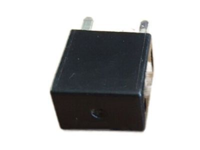
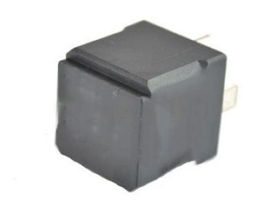
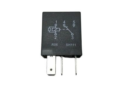
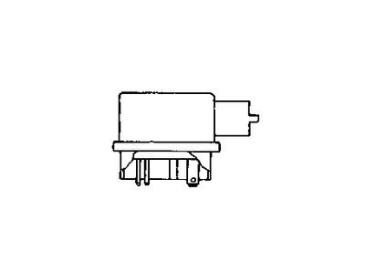
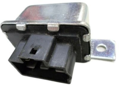
Dodge Caravan Air Conditioner Clutch Cutout
Part Number: 5233162$3.47 MSRP: $20.00You Save: $16.53 (83%)
| Page 1 of 2 |Next >
1-20 of 35 Results
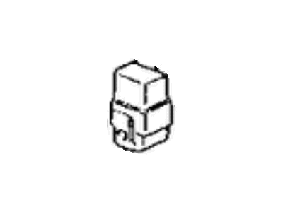
Dodge Caravan Relay
Looking for affordable and high-quality auto parts? Then you have already arrived at the proper online shop. We offer all Dodge Caravan Relay at great affordable prices. Moreover, all genuine Dodge Caravan Relay come with a manufacturer's warranty. In the long run, you would realize you have saved a lot of trouble and money with OEM parts from here.
Dodge Caravan Relay Parts Questions & Experts Answers
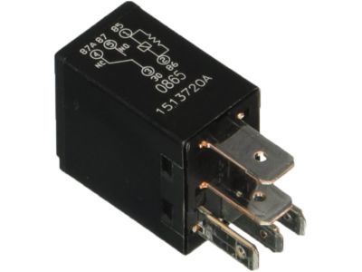
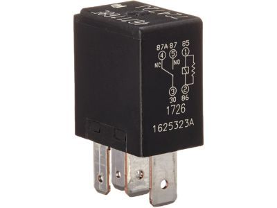
- Q: How do relays function electrical systems and how can they be tested for defects on Dodge Caravan?A: In the vehicle, there are a number of electrical accessories which employs the relay including the fuel injection system, horns, starter, and the fog lamps, among others commands electrical signals to the accessories. Relays use a low current control circuit to regulate a high current power circuit, and where there is a defective relay, the related component will not work as expected. Many relays are located in the engine compartment fuse and relay box; if a specific relay is thought to be bad, it can be pulled and checked or taken to a dealer service center, as affected relays must be replaced. ISO relays are the most often used, with numbered terminal positions denoting the circuit connections and operations, and two basic terminal arrangements. The two terminals of the control circuit attached to the relay coil and another terminal as a part of power circuit. Terminals 85 and 86 are usually the control circuit, although, particular connections are needed if a diode or resistor is present. Terminal 30 of the alternator connects to the battery voltage while terminal 87 connects the ground side of the circuit. An ohmmeter can be employed in testing the relay by placing the leads on the relay control coil to confirm on continuity testing that the resistance readings in both opposite directions are accurate. Further, there should be no continuity between terminal 30 and 87 when the relay is open. Lay the jumper wires across the correct terminals and the battery and the relay should click, this shows that the relay is working and there should be a continuity between the terminal 30 and 87. If there are any failures and according to test readings the relay should be changed.
