My Garage
My Account
Cart
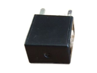
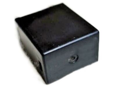
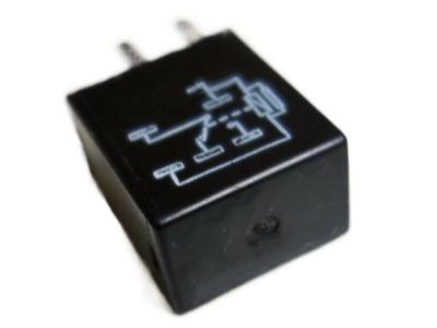
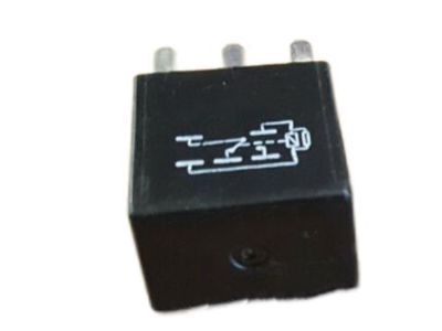
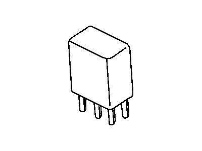
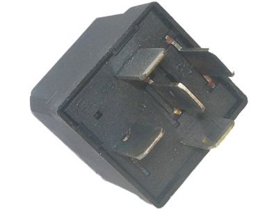
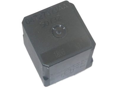
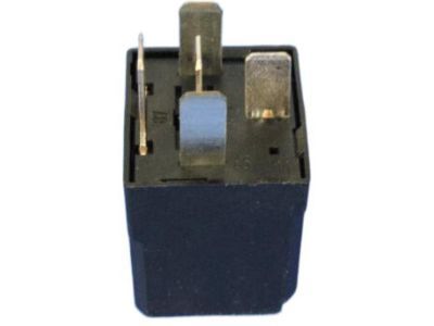
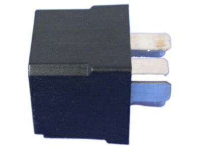
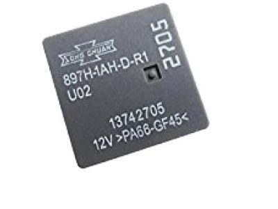
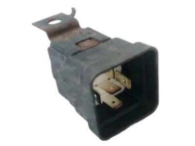
Genuine Dodge Challenger Relay
Wire Relay- Select Vehicle by Model
- Select Vehicle by VIN
Select Vehicle by Model
orMake
Model
Year
Select Vehicle by VIN
For the most accurate results, select vehicle by your VIN (Vehicle Identification Number).
7 Relays found
Dodge Challenger Relay
Looking for affordable and high-quality auto parts? Then you have already arrived at the proper online shop. We offer all Dodge Challenger Relay at great affordable prices. Moreover, all genuine Dodge Challenger Relay come with a manufacturer's warranty. In the long run, you would realize you have saved a lot of trouble and money with OEM parts from here.
Dodge Challenger Relay Parts Questions & Experts Answers
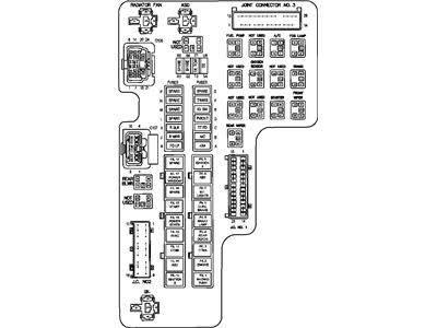
- Q: What role do relays play in electrical systems, and how can they be tested for defects on Dodge Challenger?A:A large number of electrical accessories fitted in a vehicle use relays to switch on the current to the particular component, and if a relay is bad, the component will not work as it should. Most relays are serviceable and positioned in the engine compartment fuse, and relay box which is situated at the right front corner of the engine compartment while the rear fuse, and relay box resides in the trunk below the spare tyre access panel. Still, some of relays may also be situated in other parts of the car or in different wire looms beneath the dashboard. The relay suspected to be bad is often removed and checked according to a particular procedure, or by a dealer service department or auto repair shop because defective relays are often sold as a unit. It is common to see most of the relays employed in these automobiles called "ISO" relays Many of the relay terminals are numbered to reflect their typical circuit connections and operations. Among the terminals; two terminals are for connecting the relay control circuit and are connected to the relay coil while the rest of the terminals are for the power circuit. When energised, the coil forms a magnetic field that makes the larger contacts of the power circuit to close in a bid to supply power to the associated circuit loads. Terminals 85 and 86 are conventional to become the control circuit, with special connection required if the relay has a diode or resistor. Terminal 30p is often linked with the battery voltage for the circuit loads and terminal 87 linked with the ground of the circuit. An ohmmeter can be used to check continuity through the relay control coil, the recommended procedure for testing resistance varying with the components of the relay. Relay power circuit terminals should be continuity checked, and between terminal 30 and 87 there should be no continuity when the circuit is de- energized. By connecting the end of a fused jumper wire to terminal 86 and the positive battery terminal and another end of another jumper wire to terminal 85 and the ground the relay should click implying functionality. Continuity should then be checked between the power circuit terminals After checking and if the relay fails any of the tests it should be replaced.
